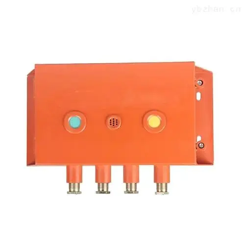
Overview
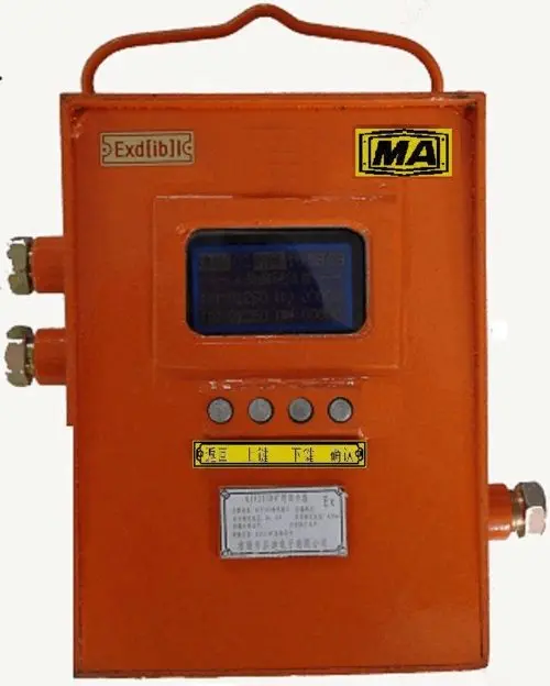
The kzc12 ethernet signal converter (hereinafter referred to as the signal converter) is an end-end companion to the integrated automated monitoring system for the entire mine and is an essential safety device for the mine。
It has resulted in a two-way conversion of rs485 signals and rj45 signals, thus increasing the utilization of existing equipment, saving investment and simplifying the complexity of wiring on the basis of established networks; and easily connecting existing serial devices to lan or internet。
The types and specifications of kzc12 signal converters with an ethnet are as follows:
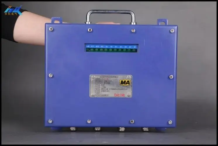
2. Environmental conditions for use
Equipment should function under the following environmental conditions:
(a) ambient temperature: 0 °c ~ + 40 °c
B) average relative humidity: not greater than 95 % (+25 °c)
(c) atmospheric pressure: 85 kpa ~ 106 kpa
(d) no significant vibrations, shocks and showers
(e) a mixture of explosive gases under a coal mine, but no damage to the insulation of corrosive gases。
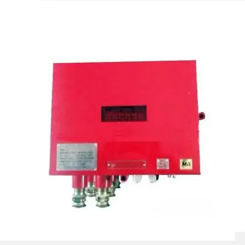
3. Rationale
Signal converters consist of dc/dc switching power modules, rs 485 and rj45 conversion modules, network ports, output rs 485 signals and rs 485 protected circuits。
Figure 1 illustrates the composition of the signal converter:
Figure 1
Dc/dc power: provides a stable and pure dc 5v working voltage for signal conversion。
Rs 485 and rj45 convert modules: it is a storage control system for communication data between rs 485 links and ethernets for connections. Process the serial data stream from the serial device and format it to make it a data frame that can be disseminated in the ethernet; judge the data frame from the ethernet and convert it to the serial device port that delivers the data response。
Output rs 485 signal and rs 485 protected circuits: the addition of mine-protected circuits on rs 485 bus is due to the long-range transmission of rs 485 bus and the fact that its transmission lines are usually exposed to outdoors, causing significant economic losses to prevent damage to equipment, including by lightning。
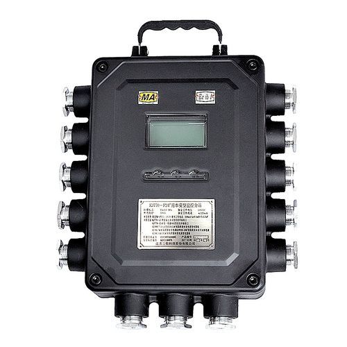
4. Key technical indicators
4. 1 power supply: dc9 v-24 v
4. 2 work currents: 200 ma
4. 3 working methods
Rs485: bipolarity, rs485
(b) rj45: 10/100 m self-adaptation approach
4. 4 communication rate
(a) rs485 mode: 1200 bit/s
(b) rj45 mode: 10/100 m self-adaptation
4. 5 transfer media
(a) rs485 method: pvc-protective signal cables with mhy32 polyethylene insulation, not less than 1. 5 mm2, distributed electrical circuits 13. 3 times/km, distributed electric capacitor 0. 06 μf/km, distributed electrons 0. 8 mh/km
(b) rj45: double winch by cat-5 and cat-6
4. 6 transmission distance
Rs485 mode: ≤10 km
(b) rj45 mode: 100 m
V. Use methodology
Figure 2 shows the internal circuit structure of the signal converter:
Figure 2
5. 1 power supply access
(a) open the upper head of the signal converter so that x1, v+, gnd at any one of the connectors in figure 2 of ben an straight current power supply access is sufficient, with attention to the positive-negative distinction
5. 2 connection to rs485 signal
A set of 485 signals (tx+, tx-) selected in the x3 and x4 links end in figure 2 are connected, and can be used simultaneously when connected to the positive and negative polar lines。
5. 3 rj45 signal connection
The module in figure 2 contains a rj45 interface, which connects the switch with the direct connection line specified in the eia/tia 568b standard。
Standard eia/tia 568b straightline requirements are: the top-to-down line order, as is the line order of the web line, is orange white, orange, green white, blue white, green, brown white, brown. See figure 3-a。
5. 4 meaning of indicator lamps
5. 4. 1 the red indicator l1 is a power signal, which is frequently lit when connected to the power
5. 4. 2 the yellow indicator l2 is the normal working light for the module, which is frequently lit, and the l2 is always lit when the double button is pressed when the an is extinguished, and only when the module is properly received and sent
5. 3. 3 the green indicator l3 and l4 are communication rate lamps that blink when the communication rate is 100m and l4 when the communication rate is 10m。