



 VIP会员


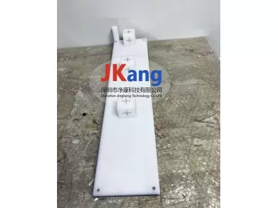
Wek-tg66 laser locator test module, wek-tg66 analogue laser qa module is a ct simulated laser qa module used to complete a second specific quality assurance check of ct scanners and indoor lasers, consistent with aapm tt66 recommendations. This clearly marked tool allows easy indexing to ct tables and facilitates a series of important qa checks, including:
• the targeting of the dragon gate laser
• distance and direction of indoor lasers
• confirmation of level and direction of workstation
• the targeting of the dragon gate laser
• distance and direction of indoor lasers
• confirmation of level and direction of workstation
Each of the three sub-pillars has a round hole of 1. 0 mm in diameter distributed along a three-dimensional x, y and z direction, where lead balls are placed at the convection。
On-board laser locator system
The test steps for the lls are as follows:
(a) open the hanger laser, vertically on the coronal face (or the part of the laser line on one side of the vector mask) and assess the maximum deviation between the lasers on both sides, in turn detecting the confluence of the lasers on the rack, if the super-comparable-water is to be adjusted;
(b) placing the laser mass control module in the positioning bed (long axes that should be placed in the center and right of the bed and vertically in the bed), as shown in figure 2, so that the cross of each module of the module is aligned with the laser inside the rack, set to the bed coordinates y = 0:
C) axle sweep using minimum layer thickness and spacing;
D) observation of scanning images to see the relationship between the internal markings (crosslines) in the matrix, indicating that cross-section lasers within the frame can accurately indicate the scanned plane and that the coronary lasers are vertically vertical with the scanned plane; if the internal markings are also visible on the non-zero plane at the same time, indicating that cross-section lasers within the frame parallel to the scanning centre and that the coronal lasers are proximate to the scanning plane b. Straight; if internal markings show different degrees of clarity at different levels or at the same level, this means that cross-section lasers on the shelf are not parallel to the scanning centre plane and that crown-face lasers are not vertical with the scanning plane, and that the super-composite difference needs to be improved
(e) to determine the compatibility of the internal laser instruction centre with the scanning centre by finding the middle module cross line level in the scanning images, removing the grid tagging tool for scanning images and observing the overlap between the module crosses and the image centre
F) a de-bed observation of the consistency of the vector lasers with the crossline of the intermediate module to determine the verticalness of the vector lasers to the scanning plane。
External laser positioning system
1. Spectacularity and mobile accuracy of external lasers
The following test steps for the co-permeability of extra-lasers and the movement accuracy are taken:
(a) open external lasers and place white paper perpendicular coronal face (or vector or cross-section) lasers in the whole imaging range, the area of the laser line on either side and assess the maximum deviation between the lasers on both sides, and in turn detect the confluence of each external laser surface, subject to adjustment;
B) stabilize the steel to the positioning bed and then check the accuracy of the movement of each party to the moving laser. Movement of parties to inspection range
It may include the scope of clinical use。
2. External laser vertical and horizontal checks
The vertical and coronary laser levels are detected using laser horizontal instruments. Adjustments if inconsistent。
On-board laser locator system
The test steps for the lls are as follows:
(a) open the hanger laser, vertically on the coronal face (or the part of the laser line on one side of the vector mask) and assess the maximum deviation between the lasers on both sides, in turn detecting the confluence of the lasers on the rack, if the super-comparable-water is to be adjusted;
(b) placing the laser mass control module in the positioning bed (long axes that should be placed in the center and right of the bed and vertically in the bed), as shown in figure 2, so that the cross of each module of the module is aligned with the laser inside the rack, set to the bed coordinates y = 0:
C) axle sweep using minimum layer thickness and spacing;
D) observation of scanning images to see the relationship between the internal markings (crosslines) in the matrix, indicating that cross-section lasers within the frame can accurately indicate the scanned plane and that the coronary lasers are vertically vertical with the scanned plane; if the internal markings are also visible on the non-zero plane at the same time, indicating that cross-section lasers within the frame parallel to the scanning centre and that the coronal lasers are proximate to the scanning plane b. Straight; if internal markings show different degrees of clarity at different levels or at the same level, this means that cross-section lasers on the shelf are not parallel to the scanning centre plane and that crown-face lasers are not vertical with the scanning plane, and that the super-composite difference needs to be improved
(e) to determine the compatibility of the internal laser instruction centre with the scanning centre by finding the middle module cross line level in the scanning images, removing the grid tagging tool for scanning images and observing the overlap between the module crosses and the image centre
F) a de-bed observation of the consistency of the vector lasers with the crossline of the intermediate module to determine the verticalness of the vector lasers to the scanning plane。
External laser positioning system
1. Spectacularity and mobile accuracy of external lasers
The following test steps for the co-permeability of extra-lasers and the movement accuracy are taken:
(a) open external lasers and place white paper perpendicular coronal face (or vector or cross-section) lasers in the whole imaging range, the area of the laser line on either side and assess the maximum deviation between the lasers on both sides, and in turn detect the confluence of each external laser surface, subject to adjustment;
B) stabilize the steel to the positioning bed and then check the accuracy of the movement of each party to the moving laser. Movement of parties to inspection range
It may include the scope of clinical use。
2. External laser vertical and horizontal checks
The vertical and coronary laser levels are detected using laser horizontal instruments. Adjustments if inconsistent。