The chargers of the cylinders had malfunctions, the fan had remained unturned and the red light was on when charged, indicating that there was voltage output to charge the cylinders and a load of currents。
But if the fan doesn't turn, even if the charger can charge, the charger can't use it, the fan doesn't turn, and the charger's internal heat spreads poorly, causing the switch to overheat and burn
How can this be maintained
In order to maintain the battery chargers, it is necessary first to have some knowledge of the basic principles of the chargers, to be familiar with the basic circuit maps, to be familiar with the metaphones commonly used in the chargers, to understand the functions of the modules, and then to learn about the basic principles of chargers。
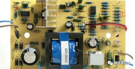
The philosophy of chargers
1. At present, battery chargers are basically designed to switch on the power source because of its efficiency, small size and light weight and lower design costs. The basic principle of the battery chargers is that 220v exchanges pass through the fuse (when the internal circuit is too large for the purpose of protection) and then exchange the direct current voltage of approximately 310v through the current bridge, followed by the conversion of 310v current voltage voltage to pulse exchange voltage through switch transformers, switch tubes, and pulsation-based integrated circuit chips (uc 3842), which are then reprocessed through the second side of the transformer before the current is handed over to the bottle to charge。
2. Switch tubes are controlled by uc 3842, which regulates the output voltage by adjusting the pwm pulse width, while output voltage is stabilized by controlling the light-linking and negative feedback through the tl 431 baseline source to the uc 3842 to control the switch opening/switch break rate. When the output voltage is high, the radium is current, lighted by the light diodes, allowing the radial to work, feedback to switches to control the circuits and lower pulse width to reduce the output voltage. A fine-tuned tl431 control of two barriers to the output power of the base source。
3. The charger's direct current output end is subject to a sample resistance to capture the output current of the charger, which can be altered by changing the value. At the same time, a sampled electrical resistance voltage will access the input end of the comparator to detect currents, when the current reaches a certain value, the comparator output flips the signal, drives the red led light to light and means that there is a load of currents; when the current is zero or less, the comparator does not flip, attention is paid to the public sign, the circuit is one point through the green led light means that there is no load of currents. At the same time, a sampled electrical resistance voltage can be accessed at another input end of the comparator to detect whether the load current is too large and, when the load is too large, the comparator output overloading signals are fed back by light to the input end-side width circuit, adjusting the output current。
4. Some models of chargers will have negatives to connect to a switch tube, which is in a state of shutdown, without voltage output, and when the vial is attached to the output end, the voltage of the battery triggers the switch conduit and thus the voltage output。
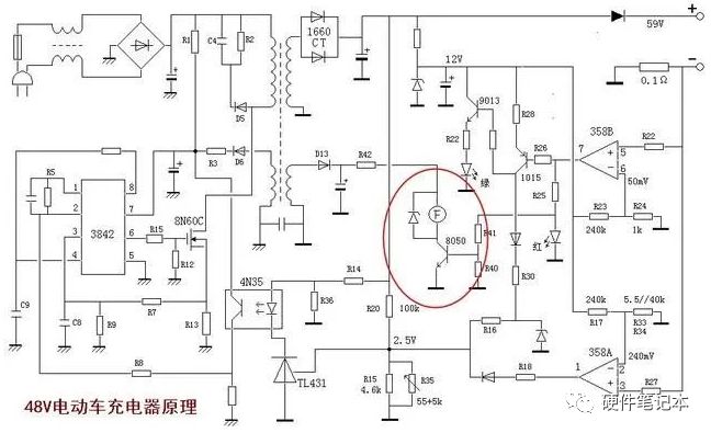
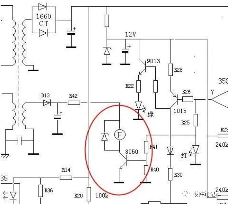
5. The fan of the electric bottling vehicle is typically 12v-powered, with a positive electrical power supply, a negative electrode of npn triodes (generally using 8050 triodes), which controls the rotation of the fan by controlling tripolar catheters, which is controlled by the output end of the comparator, such as the principle of the above image, the collection of load currents through the comparator, and, when there is a load current, the 5 foot (positive input end) voltage of the comparator 358, which is above 6 feet (negative input end) and the output of higher electrocution, making the triode 8050 catheter and the winding work。
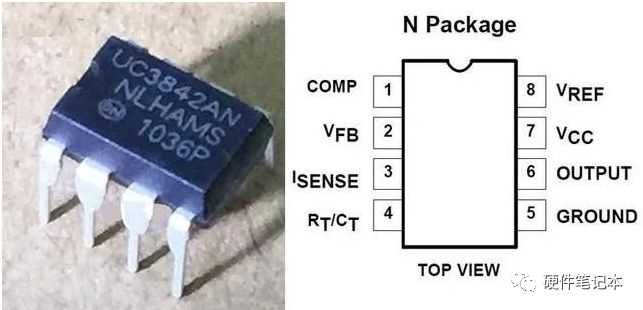
6. Uc3842, which is part of the switch, is a wide-width integrated circuit chip, each of which functions as follows:
1 foot: an output end of an error amplifier, which is a compensatory foot and is used to improve the gain and frequency characteristics of the error amplifier
2 foot: voltage feedback input end, which compares the foot with the error amplifier with the 2. 5 v baseline voltage at the side, generating an error voltage, thus controlling the pulse width, which regulates the output voltage of chargers
3 foot: the current sampling input end, which reduces the pulse width when the voltage is detected to exceed 1 v to keep the power in intermittent operation to adjust the maximum current of chargers
Four feet: fixed-time end, external oscillation resistance and oscillation convulsion, internal oscillator operating frequency determined by external resistance time constant, f=1. 72/(rtxct)5 foot: power negative pole, gnd
(b) six feet: push the output end, output the pulse-wided signal, which is used to drive the switch, internal totem pole, and rises and drops at only 50 ns drive of ± 1 a
7 foot: power supply source vcc, within 10v ~ 30v input range
8 foot: 5v base voltage output end with 50ma carrying capacity。
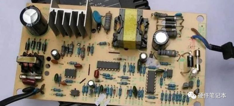
Power bottle charger failure maintenance
1. How does a fan locate a malfunction when it does not turn, having a basic understanding of the principles of the battery charger? For example, the above-mentioned pattern is that the fans are driven by 8050 npn triodes and transported by the lm358 comptroller (lm358 input and in this case used by the drop-on comptroller) to control the output of triode catheters, which are more strongly inputting the electrical pressure of the end-to-end sample resistance, the fractional pressure of the negative end of 12vs by 240 k and 1 k, approximately 0. 05 v, and the resistance of the sample by 0. 1 times, i. E., when the load stream is more than 500 ma, the output of the machine is higher, so that the red led light is activated, while the base of the 8050 triode is extremely high, the triode 8050 catheter, and the wind is working。
If the fan doesn't turn, first pull out the plug and measure the fan. The interface voltage is normal and, if the output voltage is normal, there is a high risk that the fan will fail, possibly because the wind leaves are stuck or the power sets down or the fuses fail. If there is still no output voltage, the 12v power source voltage is measured directly, and the fan interface is not measured because the negative pole of the fan interface passes through the triode switch, directly through the triode, and if it is not easy to find the end (8050 launch pole, lower left foot), the surface of the fan interface will be taken to the surface, and the red pen will be used to measure the two thrusts of the fan interface separately, if one foot has a 12v voltage, indicating that the 12v power source is normal, and if neither foot has a 12v voltage, indicating a 12v power failure。
(1) if the 12v power source is normal and the measuring drive of the tripolar tube 8050 is good or bad (the barrier measurement method can be used to cut the internal barriers between the triggers), if the 8050 is broken, the triode can be replaced and the tube is more easily damaged. If the 8050 triodes are normal (where the questioner has stated that the 8050 is normal, indicating that it is not a problem with the tube), that is, back-end-drive circuit failure, carrying (on-boarding of the cylinders) power, measuring whether the comparator output voltage is high or, if not, measuring whether the comparator input end, i. E. Sampling the resistance voltage and the baseline voltage, is normal. As shown in the figure below, because the red led lights are on, indicating that the comparator output is normal, it is highly probable that the transformation of the r41 electrical resistance to the 8050-based extremes caused the electrical resistance to increase or open the circuit or to burn the 8050-based polar voltage to remain in a low-level state and that the tripolar tube is not able to conduct it. (possibly different rationales, with slightly different controls, but very different, and based on physical assumptions, which element is damaged)。
(2) if the 12v power voltage is not exported, if the 12v steady-pressure tube is measured as short-circuit, if the current-resistance r42 is modified (extremist or open), if the filter-capacitation is short-circuited, if the whole-stream diode d13 is open, and if there is no failure to measure the two-side output end of the transformer, if there is an exchange power larger than 12v? If there is no input for the primary circuit of the ect? Focus on the public, the circuits are working。
Summarizing: the reasons for the failure of the battery chargers are many, the fan failure is relatively easy to find, and it involves little difficulty in the rationale, and the key is to understand the control logic of the comparator, which, with its basic thinking, can be measured by measuring several critical point voltages. Frequent failures of chargers include the highest rate of failure in high-pressure currents, such as high-pressure input end fuses, current diodes, filtering wave capacity, power switches, some of the high-pressure side major resistance, etc., followed by failure in the output end plume diodes, filter wave capacity, sample resistance, etc.
Also, the uc 3842 pulsed chip is also a vulnerable device with a very high failure rate, and when the device is being tested for normality, emphasis is placed on measuring some of the key induced voltages, such as the normality of the 7 foot power source voltage (generally 10v ~17v), whether the 8 foot has a 5v baseline voltage output, whether the 2 foot voltage is around 2. 5v, and whether the 6 foot has an output of pulsed aerometric signals. If direct current voltage output is high, there is a high risk of negative feedback end failure, with a focus on monitoring the normality of baseline source tl 431, the light beam and the electrical resistance in its vicinity. If the output direct current voltage is low, it may be a whole-stream diode failure, filter-capacitation failure, reduced power switch performance, drive chip failure, high-frequency pulse transformer damage, etc. Electrical maintenance requires a lot of attention, and it is in the heart that it is necessary to do so。