The electric car has entered our lives with its easy, low-carbon, environmentally friendly advantage, but its high rate of charger failure is disturbing. For this reason, based on years of discretionary maintenance experience, i have summarized for your information the maintenance methods of common malfunctions in electric chargers。
Common malfunction maintenance
Owing to the high voltage, excessive currents, electrical chargers have the highest failure rates. For example, high voltage large current current contour triodes, filter-capable, switch power tubes, etc.; the second, more vulnerable, is the output of the current-flowing diodes, the protection of the diodes, the filter capacity, the restricted current resistance, etc., and the feedback component of the pulsation mode control and the protection of the circuit。
1. Collapse of fuses
In general, the melting of the fuse tube indicates that the internal circuits of chargers are either short circuits or faulty through. This is due to the high failure rate of internal units in high voltage, large currents when chargers work long hours. In addition, volatilities of electricity grid voltages can cause instant surges of currents in chargers to melt fuses。
The maintenance method begins with a careful examination of the components above the circuit board to see whether the exterior of the elements has been burned or spilled with electrolytic fluids, smelling or not. Remeasure the electrical resistance at the power input end, if less than 20 k, indicating a local short circuit at the back end, and then measure the resistance of four whole-stream diodes, the anti-power resistance value and the resistance of two restricted currents, respectively, for short circuits or burning; the final re-measure was whether the power filter cap was properly charged, whether the switch power tube was punctured, whether the uc 3842 and the surrounding elements were punctured and burned. It should be noted that since the measurements are made by road, they may lead to errors or miscalculation of the results, they can be welded down as necessary. If the above still does not exist, measure whether the input and output power lines are internally short. In general, in the melting failure of the smelter, the whole flow of the diode, the power filter, the switch power tube, the uc 3842 are vulnerable items with a probability of damage of more than 95 per cent, which can easily be removed by focusing on the inspection of these elements。
2. Non-direct current or voltage output instability
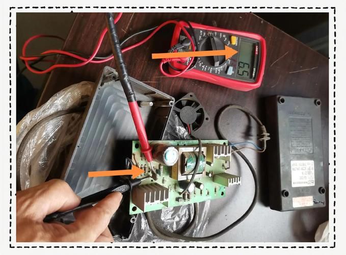
If the fuse is intact, with load inert. Such failures are due to: over-pressure, over-flow protection circuit openings, short-circuit phenomena; the lack of work on vibrating circuits; overloading of power sources; and the penetration of current diodes in high-frequency filtration filter circuits: leaks in filters。
Maintenance methods: first, whether there is damage to the various components of the hf pulse transformer using a universal meter: the direct current voltage at the output end is measured after the high frequency (hf) current piping and load short circuits have been removed, and if the output remains zero, the failure of the power-controlled circuit can be established. Finally, the damage to the current diodes and low-voltage filters in hf filter circuits is measured by a mass static measure, and the general failure is eliminated if the above-mentioned element is damaged and the new element is replaced. However, it should be noted that this failure is also caused by the breakwire or welding of the output line and that care should be taken when maintaining it。
No direct current voltage output, but fuses are intact
This is an indication that the chargers are not working, or that they are working in a protective state。
Method of repair: first, it should be determined whether the charger's transformor chip uc3842 is in the status of king or has been damaged. The test is that the 7-foot ground-to-ground voltage of uc 3842 is electrostatic and, if the 7-foot voltage is normal and the 8-foot voltage is +5 ∨, with different voltages of 1, 2, 4 and 6 feet, indicates that the circuit has been activated and uc 3842 is basically normal. In the event of low voltage of 7 feet and no voltage of the remaining tube feet, uc 3842 is shown to have been damaged. The most common damage was seven foot-to-ground penetration, six or seven foot-to-ground penetration and one or seven foot-to-ground penetration. If none of these feet were punctured and the chargers were not properly activated, this also indicates that uc 3842 was damaged and should be replaced directly. If the chip is not broken, check whether the current limit resistance at the switch is welding, welding or deforming, and whether the switch power tube itself is not functioning. In addition, the failure of power output lines or poor exposure can cause such failure and should therefore also be noted during maintenance。
4. Overproduction of direct current voltage
This failure is often caused by the abnormality of steady-pressure sampling and voltage control circuits, where direct-flow output, sample resistance, error-sampling amplifiers, photocollets, power control chips, etc. Together constitute a closed control loop, and where any problem leads to higher voltage。
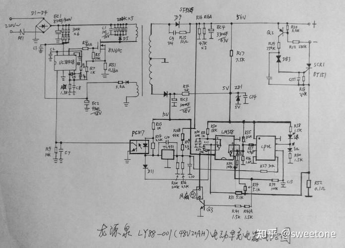
Method of repair: because chargers have pressure-protected circuits, excess output voltage first results in pressure-protected circuit movements. So with this failure, we can break the pressure-protected circuit so that it doesn't work and then measure the power main voltage in the instant. If the measured value is more than 1 v above normal, the reason for the excess of the output voltage is indeed in the control ring. This should focus on checking whether the sample resistance has been modified or damaged, or whether the precision baseline voltage source (tl 431) or the photocrystalmer (pc817) is in poor performance, deformation or damage. The precision baseline voltage source (tl431), which is highly vulnerable, can be distinguished by linking the reference end (ref) of tl431 to its cathode (cathode), a series of 1 k of resistance, and access to 5 gill voltage. If there are 2. 5 vs between the anode and the cathode and the waiter is still 2. 5 gills, the tube is good, otherwise it is bad。
5. Direct current voltage output is low
According to maintenance experience, in addition to the fact that steady voltage control of circuits can cause low output voltage, there are a number of reasons:
(1) the failure of the filtration capacitor in the current of the output voltage end may be judged by substitution。
(2) decline in the performance of the switch power tube, resulting in the failure of the switch tube to properly conduct, resulting in increased internal resistance to the power supply and reduced load capacity。
(3) the main source of the switch power tube is usually a low-value but high-power electrical resistance, which is detected as a truncated wu guard. The resistance was at 0. 2 to o. 8 times. Welding and exposure would also cause output voltage to be too low。
(4) poor high-frequency pulse transformers, which cause not only a drop in output oscillation pressure but also a lack of incentives for switch power tubes and therefore repeated damage to the switch。
(5) high-pressure straight-flow filters have poor electrical capacity, resulting in low power belt load capacity。
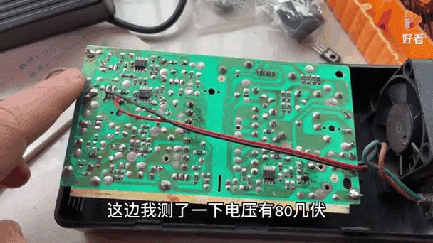
(6) the power output line is in poor contact and there is a determined exposure resistance, resulting in a low output voltage。
(7) the electricity grid is too low. While chargers can still export rated charge-grow voltage under low jade, the output voltage is also reduced when the grid voltage is below the minimum charger limit。
The maintenance method is first checked using a universal meter - whether the low-pressure straight-flow filtering caps are spoiled, whether the capacity is reduced, and whether the charge is properly discharged. In the absence of any of the above questions, current-restricted resistance to electrodes in the switch power tube and excess protection at the source poles are measured for deterioration, deterioration or welding and exposure. If there is no problem, check whether the steel core of the lower hf transformer is intact. In addition to this z, it is possible to reduce or weld or weld the capacity of the output wave; limit the current transformation value of the power output or the failure of the power output line, etc。
None of these pitfalls should be spared, and they should be scrutinized to ensure that nothing is lost。
The heat fans don't turn
The failure was mainly caused by damage to the triodes (usually 8550 or 8050) that controlled the fans, or by damage to the fans themselves or by the foliage being contained by the miscellaneous. However, some chargers use smart dissipation, and the probability of heat-sensitive resistance damage is high for chargers using this method。
Method of repair: first, a universal meter is used to measure whether the triode that controls the fan is damaged, and if the tube is not damaged, it is possible that the fan itself was damaged and that the fan could be removed from the circuit board, followed by a 12-v direct current charge (due to positive, negative pole) to see if it moves and to see if it is contained. If the electrical wires of a flat fan are moved, the fan turns, indicating that there is a break or poor contact inside the wire. If you don't turn, the fan will break. For chargers using smart dissipation, in addition to following the above-mentioned check, thermal sensitivity resistance should be checked for exposure or damage, welding, etc. However, attention should be paid to the negative temperature factor for the heat-sensitive resistance。