


1, 15w pure a-ray circuit maps and principles provide an overview of the current market of hfi-based magnification products with a high output power above 100w, with a significant proportion of alpha-magnification products in 50100w. Larger power reserves are certainly good from the point of view of high security, but they are worth considering from the point of view of energy savings. Because of the low efficiency of pure a, you enjoy wonderful music, and about 70 or 80 percent of the electricity is turned into heat. A pure alaformation with a 50-w per acoustic output power, which, if measured at 30, would be 330-w of static power, a joke that would be “screw watermelons in the fireplace”. It is often the case that pens buy credit while helping their candidates: many people, although dumped on the sound of pure aluminum, often suffer from their “high fever” working conditions。
High efficiency is also a fatal weakness in electronic management. The market economy is ruthless. Proof of this is the fact that several of the country's famous producers of bold machines, such as spock, ober and grand oracle, have launched their own transistors. In accordance with our national conditions, the average wage earner has more than 20 square metres of living space and usually has the living room or bedroom as the sound room. If the soundbox is more sensitive than 89 db, the general appreciation requirement is met by a 1020 w of pure alpha. If we keep our ears up to the loudspeaker in environments like the cabarets, the hearing will fade. Moreover, it is not appropriate to argue in peace with the right-hand neighbourhood. So, if we produce some better sound-colored power around 15 w, static power is spent below 100 w, there will be a market. Unfortunately, it's a blank. There's a 20 in the golden voice of japan. 20 w in each channel
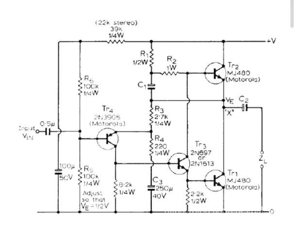
3. There is a reputation for quality, but the price is prohibitive. Now, domestic producers seem to be climbing, with greater power and heavier weights, but less and less good. Why don't you make some "good or expensive" work and put it on the market? And with that in mind, we designed this 15-ww pure-a-acrylic device, trying to try something about it. I. Circuit principle 1, hcd circuits by vt1 and vt2 form a differential zooming circuit with static currents of approximately 0. 5ma per tube. R3 is a vt1 charge charge resistance, a direct connection between vt1 and the thrust level vt4. The output stage consists of two large-power transistor tubes of the same type of npn vt5, vt6 instead of a complementary symmetrical roller circuit. The output tube vt6 is co-launching the polar circuit for loads, while the vt5 is radio-extending the circuit, so it's asymmetrically magnified
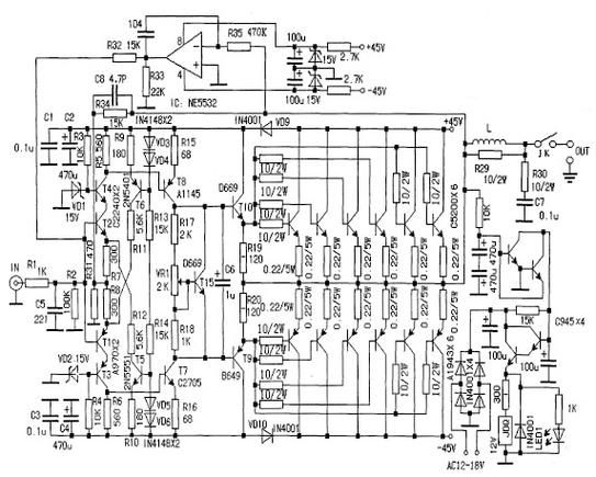
4. However, experimental tests showed that the entire amplification circuits were defiant at the time of the cancellation of the great ring negative feedback (r5 short circuits), and that it was mainly occasional. This is due to the promotion of class circuits. The promotion of circuits is one of the most characteristic circuits of the machine, and its effects and effects are far greater than those of the traditional rc-run circuits. Vt4 is a fusion split reverse circuit by which it collects the electrodes and discharges the polars to produce a pair of signals equal in size and opposite direction. Vt4 for output tube vt6 is an output circuit with a voltage magnification factor of less than 1. The signal from the vt4 hologram output is added to the base pole of the output push tube vt3 by communicating the light-emitting vd1 with little resistance. The positive guidance contour pressure of vd1 is about 1. 9v, which can be considered as a small noise-silent diode, which allows the direct current voltage of vt3 to eec at both ends of r7
5. Essentially unchanged, approximately 0. 7v less than the stable pressure of vd1. For communication signals, r7 is linked to the ejection resistance of vt3. Vt3 and vt5 form the same polar darinton complex. The upper arm is thus composed of a first-stage co-radiation magnification circuit (vt4) and a second-stage radio-output circuit (vt3, vt5), while the lower arm of a reductive circuit consists of a first-stage ejection circuit (vt4) and a first-stage co-jection magnification circuit (vt6), which can be seen as as asymmetrical. Therefore, the current magnification factors for these tubes need not be matched when selecting magnifying tubes. This is particularly important in the case of large-scale plant production, which can significantly reduce costs. The prototype's pipe values are as follows: 1=2=110, 3=50, 4=90, 5=70, 6=90. In other words, priority is given to vt4 for the larger tube
6 and vt6. The open-enhanced voltage multiplier of the jcd circuit is about 504, and the closed-enhanced voltage magnification factor is determined by r4 and r5 and is about 15. 7. The theoretical maximum efficiency is 50 for the alpha-reducing power magnification circuit, with the machine actually measuring the maximum output voltage of 11v and the folding output power of about 15w (8) and static power consumption of about 40w, thus the maximum efficiency of 37. 5. When a signal is not entered, the efficiency is zero, and the power of 40w is consumed almost entirely by two output tubes, so that a sufficient area of radiator is added and the ventilation is assured. In summary, the power release has the following characteristics: 1. The current magnification factor of the power output tube does not need to be paired; 2. The conventional self-lifting circuit has been replaced by a proximate circuit designed by a penr, with a good frequency response; 3. The output voltage is high; 4. The circuit is simple, easy to adjust and easy to produce. 2. Steady voltage power due to ocl circuits
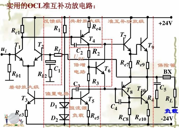
7. The output end is linked directly to the speaker and should normally be fitted to protect the circuits over time, but this part of the circuit has been omitted because it uses a 17v double-circuit steady voltage power with short-circuit protection and soft starter. Both positive and negative voltage circuits are adapted by means of a total electrode output, which is efficient and has short circuit protection, but cannot be self-started. Vt7, vt9 forms a composite power adjustment tube. Vt11 for sampling magnifying tubes. Since the base pole of vt11 is grounded, the launch level must be 0. 7v to enable it to operate in a state of magnification. So the lower end of r19 cannot land, but it is to 17v. So, if the negative output power is short-circuited to the ground, the volt11 launch pole and the base pole will have zero volt, thus closing vt11, so that the tubes vt9 and vt7 will be adjusted to the end of the currents of the base pole, which will result in zero power being exported. Due to positive, negative voltage
8. Roads are symmetrical, so negative power voltage can also be zero when there is a direct power-to-ground shortcut. This is why the output end of the power-release circuit saves the use of loudspeakers to protect the circuits. In the event of a short-circuit blast from one outlet, the other outlet would not have access to the power voltage as a result of the above-mentioned protections, so that the loudspeaker would not have large direct currents passing through, thereby effectively protecting the loudspeaker. The output voltage of the power is essentially determined by the stable pressure values of the vd4, vd5, two steady pressure tubes, which are approximately 0. 7v lower than their stable pressure values (i. E. Minus vt11, vt12), so that the two steady pressure tubes are carefully selected for pairing. Enter the end filter capacitors using two 4,700 f electrolytic capacitors on each side and associated, while the end of the output filter capacitors use only one 10-f non-polar capacitors on each side. It's measured by a sample, when the output current is 2. 4a (full load)
Small wave voltage: 0. 8 mv positive and 1. 25 mv negative. In addition, the wave shape is not a 100hz sawn tooth, but rather a noise form with a wider spectrum. The smoothing performance of the power source is due to a certain voltage magnification factor in the adjustment tube for the electrostatic voltage circuits of the total electrode output, and to the sampling ratio of the sample circuits equal to 1, the voltage changes at the end of the output are condensed directly through vd4, vd5 to the launch poles of the sample magnifying tube vt11, vt12. The power source also designed softly activated circuits in order to eliminate the sound of “show” caused by the shock current of the loudspeaker when the general ocl circuit is opened. The working method is as follows: the positive voltage on the filter capacitor c3 is charged to c5 via r10 and the voltage on c5 rises exponentially. The voltage is added to the positive output end by r12 and vd2, and also by r16
10, provide currents for the vt12 launch poles, so that the negative power is also activated. When the power voltage reaches normal, the positive output voltage is channeled by r14 to one-way controlled silicon vd3 by providing a trigger voltage. The anode voltage was lowered to less than 0. 7v after the vd3 transport, so the diode vd2 was closed. C5 on voltage discharge via r12 and vd3. The delay is determined by r10, c5 time constant, which is 0. 33 seconds in this case, without any sound in the soundbox when it is on. The power source is highly efficient and the output voltage can remain stable when the voltage between the tube collection pole and the transmitter pole is reduced to 1v. If the municipal voltage voltage voltage is 220v, the input voltage of the steady voltage circuit is set at 22v (with a rated load), so that the steady voltage power will remain in its optimal state at 10 when the municipal electricity changes. If down to 7v by adjustment tube pressure
11/ calculates that the tube consumes approximately 17 w at full load of 2. 4a and therefore requires only smaller radiators, at which time efficiency is above 70. When adjusting pipe pressure to 3v, the efficiency is 85. In summary, the electrical circuits are characterized as having a soft start function; a protection function with a positive or negative power supply of short circuits or simultaneous short circuits, which saves the acoustic protection of circuits; efficiency, which is about 7085 or more; and low-print wave coefficients. Ii. Production and adjustment of element 1. Elemental output tubes vt5, vt6 select 2 sc3281 of toshiba, between 70110. 2 sc 2922 was also selected for the experiment but was found to be prone to high-frequency self-motivation. 2sd401 for vt4 selection nec with a value of 7090, and 2sd401 between 5070. Vt3, vt4 when the value of the output tube is over 100
12 optional 3dg130 (3dg12). The input level vt1, vt2 can select 9012 or 9015, which is around 100 and is not too high, but requires pairing; or the p groove type transistor, which should not be less than 40v (since no such tube exists on hand and is not tested). Resisting power r6, r10 shall be selected above 1w, r7, r16, r19 shall be selected above 12w, the rest not required. Resistor r9 uses two 1w, 0. 51 resistors combined for sampling purposes. Vd4, vd5 should be selected for power above 1w. One-way controlled silicon can select any type of 1a current. Vt7, vt8 of the power component selects mj2955 and 2n3055 or other complementary pairs, which are more demanding, preferably greater than 80. Push pipe vt
13, 9, vt10 selected medium power tubes 3ck9, 3dk9, etc., with values between 5080. Sampling magnifying tubes vt11, vt12 selected 9014 and 9015 with values greater than 100. It is also important to note that the values of both positive and negative power tubes should be similar, i. E. Roughly paired. Capability c1, c6, c7 select detergent or polypropylene. The voltage power input filtration capc3, c4 uses four 4,700f35v high quality electrolytic capacitors in combination. Power transformers should have a power capacity of not less than 100 va, secondary exchange voltage of double 18 v, current of more than 3a. 1 n5401 for flow tubes. 2. Adjustments to the power component of the element need hardly be made. If the power is not self-started, the value of r10 should be reduced appropriately, but as much as possible with full capacity, to increase the delay. The adjustments for the credit segment can be grouped into two; one is the adjustment of r2 to equal zero to the output end level; and the other is the adjustment of r6 to equal 0. 3v to the pressure down on r9, at which point the final static current is about 1. 18a. Note that electrical currents can be adjusted slightly at the beginning, e. G. 0. 9a, and then later to the above specified values after a period of preheating. 3. The adaptation of the circuit to the power discharge circuits can be converted to tl circuits with minor modifications, at which point the steady voltage circuits can save the negative power component. Otl circuits, although tested for technical indicators, do not have the same quality as ocl circuits. The otl circuit, through the use of the output capacitors, although affecting the frequency characteristics, ensures the safety of the speaker. It is not repeated here. The main technical indicators for this facility are as follows: maximum output power 15w (8); frequency response 5hz 44khz (1d)









