


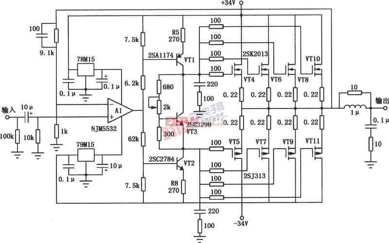
Simple audio discharge circuits are complete (six simple audio discharge circuit designs are detailed) and simple audio discharge circuits (i) have only 17 parts to play, but they have unexpected effects, the echoes are true, the frequency is flat, the resolution is high and the power can reach 50w. This utilised circuit is a piece of work and is particularly suitable for starters. For specific circuits (only one channel is drawn), 1/2w electrical resistance, c2 and c4 voltage, q5, q6 high power tubes 2sc5200, transformer capacity greater than 200w, secondary output voltage ac22v*24a. Debugging method: the unit generally does not need to adjust and the mid-point voltage can be considered normal in +-50 mv, otherwise the resistance value of r2 can be adjusted by increasing r2 if it deviates from the voltage height and by reducing it. A simple audio discharge circuit (ii) is described as a quasi-complementary ocl circuit consisting of ne 5532. The audio power amplification circuit uses an operation amplifier-based driver, and the crystal triode vt1~vt4 consists of a composite complementary symmetric circuit to act as a power magnification. Total circuit gain au = (r1+r3)/r1, rl for speaker. The process of communicating signals is similar to the simple complementary symmetric power amplifiers. Rp1 regulater gain, rp2 to adjust mid-point voltage. This circuit will succeed with a simple debugging, and the tone of the replacement of the different transporter will change, and the diy will have all the fun. The disadvantage is that the power is small, so that the power delivered can be increased and pressured to a positive or negative 15v, and the voltage of the back-up









