


Three-way bridge reversers. Figure
1) a 3-phase bridge reverser
The circuits and their wave shapes are shown in figure 1 (a) for the circuit structure and figure 1 (b) for the output voltage wave shape. In figure 1 (a), n is the intermediate point of the load and o enters the midpoint of the power source for the current, which is a false point for discussion purposes. The upper and lower switches on each arm of the bridge rotate through 180. Thus, the flow of electricity through each load is continuous. We call it 180. Transient 3-phase full bridge reverser. Six power switch tubes are conductive in vl, v2, v3, v4, v5, v6. In the analysis, za = zb = zc = z, assuming three phase loads are symmetrical. These are discussed below in both resistance and sensory loads。
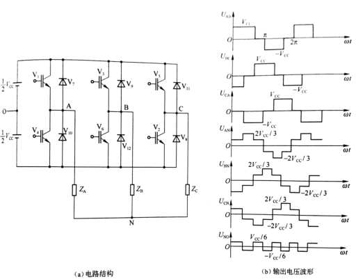
Figure 1 3-phase bridge reverser circuits and their wave shape
(1) barrier load
As can be seen from figure 3-16(b), the linear voltage of uab, ubc and uca is a rectangular wave with a width of 120. The band is a earthvcc with a phase difference of 120° for each voltage; the phase of uan, ubn and ucn is a six-step ramp with a band of ±2vcc/3 and a width of 60 for each step. The phase differential of the voltage is 120°; the voltage of uno between point n and point o is a square wave with a frequency of three times the base wave frequency and a value of vcc/6. Each of the load currents is identical to its phase voltage and is a six-step wave。
The output line voltage and the output phase voltage are expressed in the furier class, respectively
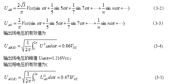
Output phase voltage peak uan(p)=o. 666vcc。
Available from modes (3-2) and (3-3), output line uab's base wave peak uab(p) = 1. Lv cc, base wave effectiveness
Uabi(e) = 0. 78 vcc; uani(p) = 0. 636 vcc for output phase uan, uani(p) = 0. 45 vcc。
(1) sensory load
The load of the reverser is:
, load angle
, by load
Different, you can divide the retrovert process into
Two scenarios。
Situation
It is assumed that the original state is vl, v6, v5, as shown in figure 2 (a). The ia, ib and ic in figure i are currents for a, b and c, respectively, and i is currents for input power. The direction of the currents is shown by the arrows in the diagram。
When the switch pipe v5 is broken, the lc will not be interrupted immediately, but will be able to continue through the diode v8, thus completing the conversion process of the power-down switch on the c-bridge arm. The status of v1, v6 and v8 conductors is shown in figure 2 (b). As the currents continued, the currents declined and grew in reverse directions after zero. Due to load
\\v8 has a continuation time of less than \\3 and i'm not moving in the same direction. Inverters output voltage waves in the same shape as resistance loads, as shown in figure 1 (b)。
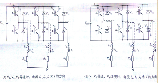
Figure 2 180° transposed 3-phase full bridge reverser in
Time shift process
In the light of the above, in the sensory load
There are two working modes for the 180° conductor three-phase full-bridge reversers: three power switch conduits and two power switch conduits, and one diode continuation, as shown in figure 3 (a) and (b)。
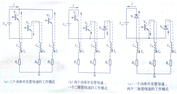
Figure 3 180° conductivity three-phase bridge reversers in
Working mode of the time
Cases
Assuming that the original state is v7, v6, v5, the direction of currents ia, ib, ic and i is shown in figure 4 (a). When the power switch v5 is off, the current ic doesn't mutate, and it is continued by the diode v8. V7 and v8 continue simultaneously, changing the direction of current i and inputing power transmission energy from the load side into the direct current, as shown in figure 4 (b). When the v7 is closed, vl leads, the current ia changes direction, re-emergences two power switch conduits, and a working pattern for a diode continuation。
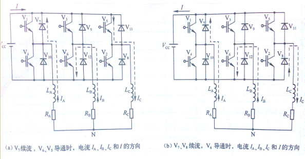
Figure 4 180 ° conductivity 3-phase full bridge reverser process at 2
In the light of the above, in the sensory load
There are two working modes of a three-phase fully-bridge transformer of 180° conductivity: a power switch conduit, two diodes and two power switches, and a bipolar tube continuation, as shown in figures 3 (c) and (b)。
2) a three-phase bridge reverser
Figure 5 shows the rationale for the 120o-conductor three-phase bridge reversers. In current-type reversers, electrons are used as energy storage components, and when l is large, input current il is near constant because the current in l cannot mutate. The time-series of the driving signals of the power switches varies by 60°, and the power switches follow the order of vl, v2, v3, v4, v5, v6, each at 120°, so that, at any given time, only two power switches are connected。
If the load is connected, the connection to the current-type triple reverser is shown in figure 5. For resistance loads, the current ivl ~ iv6 is 120° wide and the rectangular wave is il high, while the wave shape of the carrying current iab, ibc and ica is steep, as shown in figure 6。
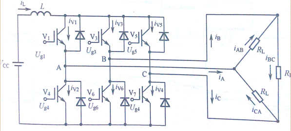
Figure 5 120° principles for a three-phase bridge reverser figure
If resistance loads are y (star) relays, the wave shape of the three-phase transient reverser circuits and phase currents at 120° is shown in figure 6(b). Load phase currents ia, ib and ic wavelengths of 120° wide and rectangular waves of il。
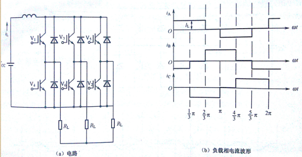
Figure 6
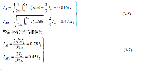
The average square root value of the load current in figure 4 and figure 5 can be calculated in the lower form (example a)
The current three-phase bridge reverser is often used for motor velocity, at which point the load is sensory. Assuming that the circuits of the electric motors are connected, the wave shape of the load current i ab, i bc and ica, even though it is a ramp wave, is unlikely that the current will mutate due to the presence of the sensory load and changes in the current will take time. The current-type 3-reverse transformer circuits and work wave shapes with electricly driven loads are shown in figure 8。
In figure 8, the circuits of the motors can be equivalent to a gibo voltage associated with the electrons
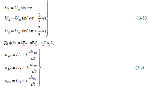
As can be seen from figure 8 (b), currents iab, ibc, ica are still, like resistance loads, the six-step step wave (only iab wave shapes are given in the figure), but the currents will vary according to certain patterns due to the electro-motive perception. It is understood from the formula (3-9) that wire voltage uab, ubc, uca, diab/dt, dibc/dt, and dica/dt will generate excessive voltage during the replacement, as shown in figure 8 (b)。
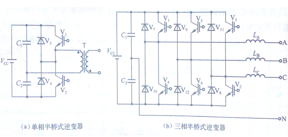
Figure 8 current-type 3-reverse transformer circuits and working waveforms with electro-motive sensory load triangles









