


Lock amplifierIt is a device for the detection of weak signals, which are often flooded with noise, and lock amplifiers can extract the weak signals from the noise and measure them accurately. The lock amplifier is a weak signal detection method based on a mutually drying method, with the core of which is a sensitive detection technique, using reference signals with the same frequency and fixed phase relationship as to the signal to be detected as a benchmark, filtering out noises different from their frequency and thus extracting useful signal components。
The most basic treatment of a weak signal is amplification, with the traditional amplification process magnifying the signal while also magnifying the noise, and any amplification operation would result in a decrease in the signal signal noise ratio without a banding or filtering process. Therefore, filters must be used first to purge signals and increase the cell noise ratio in order to achieve accurate measurement of the weak signals。
Assuming that the signal to be amplified is a 10 nv, 10 khz sine wave signal, the good low noise amplifier has about 5 nv/√hz input noise. Consider the following:
1 the bandwidth of the amplifier is 100 khz, with an increase of 1,000, with a magnification signal of 10 uv (10 nv x 1000) and a wide-frequency noise of 1. 6 mv (5 nv/√hz x √100 khz x 1000). There is no way to measure the output signal。
2 add an ideal filter with a quality factor of q = 100 with a central frequency of 10 khz and all signals within a bandwidth of 100 hz (10 khz/q) to the amplifier. The output signal remains at 10 uv, while the noise size of the filter belt is 50 uv (5 nv/√hz x 100 hz x 1000). The output noise is still much larger than the output signal and cannot be measured。
3 add a sensitization detector (psd) to the amplifier. Psd can detect a signal of 10 khz with a bandwidth of only 0. 01 hz. Under this bandwidth, the output signal remains at 10 uv and the noise is only 0. 5 uv (5 nv/√hz x √. 01 hz x 1000)。
The noise ratio is 20 and the signal can be measured accurately。
Sensitivity detector
The sensitivity detector (psd) is equivalent to a very narrow band-banded filter, with a basic module consisting of a multiplication module that multiplies the input signal with the reference signal and a filter module that uses low filters to multiply the multiplier result. Sometimes the psd also points to multiplication modules, which do not contain filter modules. As shown in figure 1。
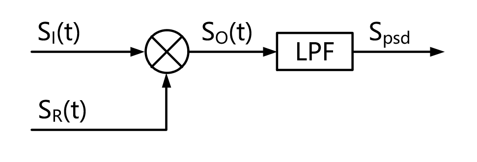
Si(t) is a time-based input signal mixed with noise, and sr(t) is a reference signal that has a fixed frequency relationship to input to be detected. Psd combines a signal channel to be measured with a reference signal channel, i. E. It can form a complete chain amplifier functional structure, known as a single stage lock amplifier. Its structure is illustrated in figure 2。
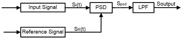
Signal channel into the psd module can be defined as: si(t)=ai sin(wt+)+b(t)
Of these, w is the frequency of the signal to be measured, ai sin (wt+) is the signal to be measured, and b(t) is the total noise。
If the standard reference signal for reference signal channel output is defined as: sr0(t) = ar sin (w0t + obtained)
The two-way signal entered the psd module for multiplication and obtained the following output:
Spsd0 = si(t)sr0(t)=aear sin(wt + φ) sin(w0t + successful)+b(t)ar sin(w0t + successful)
=0. 5 aiar cos(t+ φ - successful) -0. 5 aiar cos(t+ + + successful) + b(t)ar sin (w0t + successful)
Constant w0 = w, i. E. The reference signal is equal to the frequency of the signal to be detected, at which point the standard reference signal for the reference signal channel output is:
Sr(t) = ar sin (wt + successful)
Output: spsd =si(t)sr(t) = aear sin(wt + φ) sin(wt + successful) + b(t)ar sin(wt + completed) = 0. 5 a









