I. Distinction between residual and zero-series currents
In order to prevent inter-person access to electricity and damage to distribution lines for various reasons, causing accidents such as fires, and to ensure thermal stability of equipment and lines, the relevant norms in force in the country, such as electrical design, construction and so forth, have introduced the need for site failure protection in low-pressure distribution lines. Article 4. 4. 10 of the national standard gb 50054-95 design instructions for low-voltage diffusion design clearly identifies two methods for the use of site failure protection: zero sequence current protection and residual current protection (also referred to as leak current protection). The basic working principles of the two current protections are the same, but the scope of use, installation, etc. Are different。
Zero-sequencing current protection specific applications can be fitted with one current sensor (c. T) on each of the three-phased lines, or the tri-conductor line can be crossed through the zero c. T., or a non-sequence c. T. On the neutral line n, using these c. T. To detect the three-phase current vectors and the zero-sequence current i0, ia+ib+ic=i0, when the three-phase loads taken on the line are fully balanced (without ground failure and without consideration for leaks in the lines, electrical equipment), i0 = 0; when the three-phase loads taken on the line are uneven, i0 = in, the zero-sequenced current is an uneven current electrical in
When there is a ground failure in a particular phase, there is necessarily a single-stage failure current id, at which point the zero-series current i0 = in+id detected is the vector sum of three-phase unbalanced currents and one-stage current。
The specific approach to remaining current protection is to have one c. T on each of the tri-conductor lines measured and neutral n, or to have the tri-conductor cross the line along with the n line through a zero-order c. T., to receive the tri-conductor vector and the ia+ib+ic+in, which is zero when there is a single-phase failure, regardless of the balance of the tri-load (strictly the normal leak of the circuit and the equipment); when there is a failure of a single line, the failure stream passes through the protective line pe and the metal components connected to the ground, i. E. The ia+ib+ic+ic+in00, at this time the value is normal leakage of the attached stream id+。
As can be seen from the above analysis, both zero-sequencing current protection and residual current protection are based on kirhoff's electrical law: algebraics and the equivalent of zero, i. E. Σi = 0, into any nodal point of the circuit, and both use zero-sequenced c. T. As a sampling component。
In normal circuits and electrical equipment, the vectors and the equivalent of each phase of the current are zero (zero sequence current protection is assumed not to take into account the imbalanced current), so that the second side of the zero sequence c. T has no signal output (in the case of zero sequence current protection, you have avoided the imbalanced current) and the execution element is inactive. When ground failure occurs, the vectors and non-zeros of each phase of the current generate magnetic fluxes in the ring iron core of c. T., the zero c. T., the secondary sensor voltage of the zero c. T. Enables the execution element to move, boost the detachment device, switch the power network for the purpose of protecting the site from failure。
Ii. Remaining current intersensors
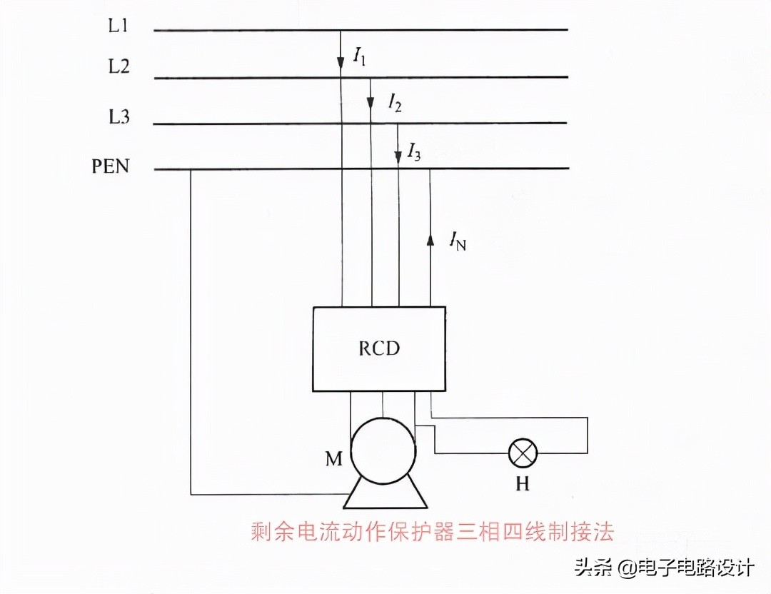
For example, the three-way four-way system, as shown in the graph, is a three-way four-way circuit for the remaining electrical flow protection. When normal, i1+i2+l+i=0 (vectors and) the remaining electricity flow is not actionable. Il+i2+in+in+in≠0 (vector sum) when the equipment is leaked or electrocuted, the remaining electrical flow is activated and the power is cut off。
Similarly, the same is true for single- and tri-route circuits, noting that the pe line cannot pass through the remaining current sensors。
Iii. Zero sequenced current sensors
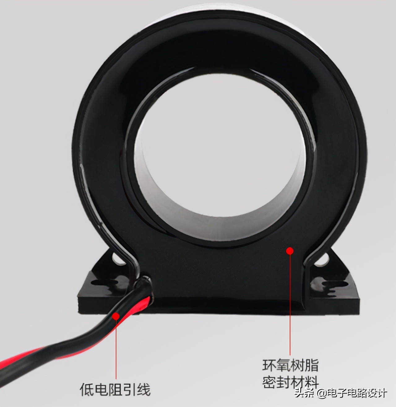
The function of the zero-sequence current intersensor is to check whether the zero-sequence fluctuation is excessive. If a single or two-stage failure occurs in the low-voltage distribution system, the malfunctioning current returns to the power transformer via the pe line or the working relay。
In order to detect the failure of electricity currents in this part of the site, the pe line or the work line must first pass through a zero sequence current sensor and then be connected to the transformer. If the neutrality point of the transformer is directly connected, the ground failure current is directly connected to the power transformer through work, rather than to the zero sequence current sensor, which cannot detect excesses。
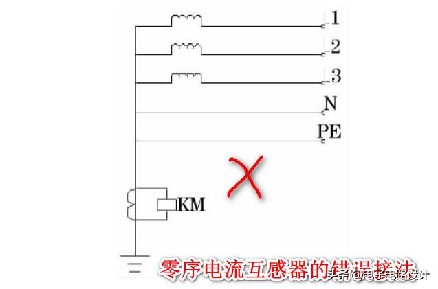
The following is a zero-sequence fluctuary interceptor error connection, whereby the zero-sequence interceptor will act only when the line hits the ground; if the line touches the pe-line, the malfunctioning current will return to the transformer from the pe line and will not pass through the iron of the zero-sequenced interceptor, so that the second side will not detect the current and the zero-sequence interchanger will not act, thereby losing the function of installing the zero-sequent interceptor。
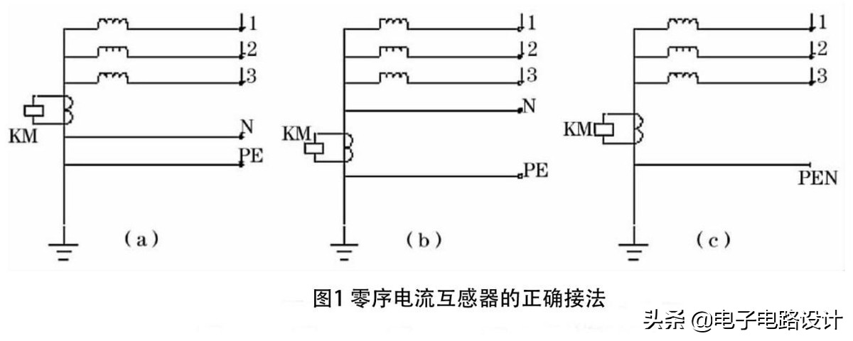
The correct transposition of the zero sequence current sensor is shown in figure 1 (a). In this connection, when the line hits the ground or the pe line, the zero-sequent current sensor moves; when the three-phase current imbalance exceeds the allowable value, the uneven current will make the zero-sequence current sensor actually function as an electric current protection via the n-line。
If a zero-series current sensor is required to act when the power leak exceeds the allowable value, and if the three-phase imbalance does not, the zero-series current sensor can be connected to figure 1 (b). At the time of the three imbalances, the imbalanced current flowed through the n line, but not through the zero sequence current sensor, so that the zero sequence current sensor did not move。
For tn-c systems, the zero-sequence current interceptor is connected to figure 1 (c). Whether the line hits the ground or the pen line, the zero sequence current sensor moves as long as the leak or the triple imbalance current exceeds the allowed value。