


Switch the powerThe pfc circuit, which is the circuit for the calibration of power factors, is operated by a power switch which is a portable load, has a low power factor, makes the grid less efficient and, when added to the pfc circuits, can achieve a power factor of 98 per cent。
We first need to know that in the communication equipment, there is a resistance load, an acceptable load, a sensor load。
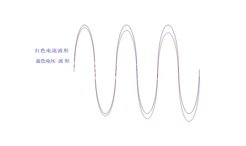
The resistance load has a power factor of 1 because its current and voltage wave shape are the same
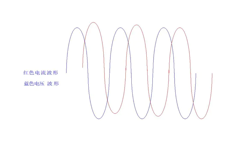
Capable load
The current is 90 degrees above the front
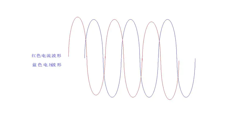
Sensory load
Sensitivity load delayed voltage 90 degrees
Sensory loads such as transformers, electric motors, and a portable load are equipment with filtering caps at the back end of the current。
The power factor for the portable and sensory loads is low, the power supply is inefficient, the capacity load and the sensory load are weak, the large current load is disturbed by current malformations, which can interfere with the grid and itself。
Therefore, for the capacity load, the capacity load of a switch power greater than 100 w, e. G. Computer power, liquid crystal television power, etc., requires an increase in the power factor to correct the circuit, so that the current phase can be at the same level as the voltage phase by changing the load characteristics close to resistance。
Pfc power factor correction is in two categories
Passive pfc
(b) a co-linking sense between the whole bridge and the filtering cap, using the non-variable properties of the electrical current to buffer the charged current, to modify the malformation of the current shape of the grid line, to increase the power factor and to mitigate electromagnetic interference, but only to increase a little power factor, which is inefficient and suitable for small power sources。
Active pfc
The active pfc uses electron components to be decapacitate the acoustic form of the acoustic current wave, so that the electric voltage and current phase are the same, so that their properties are close to the resistance load and the voltage and current are the same。
The power source is the capacity load because of a capacitor at the back end of the whole-flow bridge, repeated charge to the capacitor, resulting in powerlessness, alteration of the circuit structure, a chain of circuits that separates the capacitors from the circuit and, in fact, an additional boost circuit。
A boost circuit is connected after the current is complete, the direct current re-charges to the cap, the direct currents are converted to high-frequency pulse direct currents using boost switches, a stable direct current voltage is obtained through the diapolic integrated currents, and a back-stage switch is supplied。
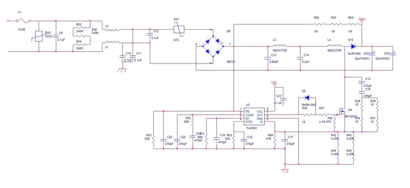
The pfc circuits generally push the direct-flow 300v pulse voltage up to 380v for several reasons, including reduction in wear and tear, reduction in the volume of electrons, too low for the spatial stability of the chip, and unstable voltage。
Pfc is also a very vulnerable circuit, with high voltage, easy access to switches and current tubes, back-up switches to break through, and damage to the outer parts of the switch and current tubes and power chips due to delays in pfc protection。
My years of experience in developing software hardware for single machinesCircuit maintenanceExperience, learning circuits, paying attention to keeping you from getting lost. Your praises are the most important motivation for me to share experiences. Please leave a message。









