


Design and application of plc teaching simulation control board
YesElectronics for electricians♪ against the background of the evolution ♪AutomationThe application of the field is becoming increasingly widespread, as is the teaching of plc courses, which play an important role in developing students ' excellent engineering awareness, strong practical skills and keen innovation as basic courses in electronics for electricians. The plc teaching experiment system is being improved and expanded to be more relevant to school education and scientific research. Using plc simulation panels to simulate various electrician electronic control objects and to graphically display the main actions of the objects, teaching efficiency can be significantly improved by replacing software to simulate different control objects。
Basic composition of plc teaching simulation control boards
Plc teaching simulation control boards consist of three main components: hardware simulation of controlled objects, signal adjusters, and plc. Hardware controlled simulating objects: simulate components such as operative components, sensors, etc. Of the controlled object by means of a control panel in order to transfer information between the controlled operational status and control control commands, and achieve a hardware simulation of the controlled object。
Signal adjusters: hardware and software simulations for hardware connections between controlled objects and plc and their signal adjustments. Signal adjusters collect and control plc i/o port parameters and communicate with the host. Together, these modules form the entire teaching simulation control board, which is visual and convenient。
The entire control panel process is to collect i/o port parameters of plc from the signal processing panel, process them with a signal adjusted version and send them to the cpu in the plc for further processing, send processed data to the subject under control, send computer objects and feedback control signals to plc via the usb port, which is controlled according to a program developed by the user。
Plc teaching simulation control boards meet not only experimental teaching needs, but also the requirement to simulate debug applications in the physical control of production lines。
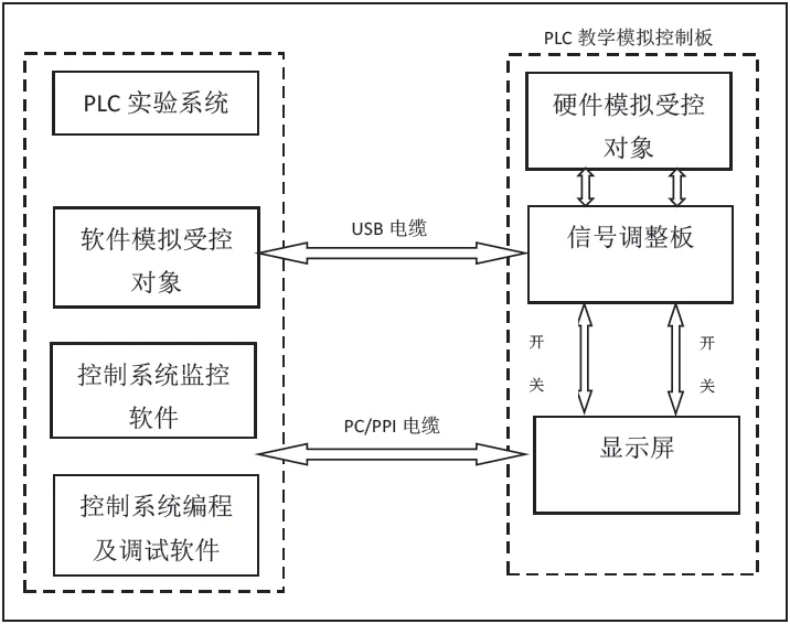
Figure 1 basic composition of plc teaching simulation control board
Ii. Working model of plc teaching simulation control boards
The lc teaching simulation control board has two operating models: computer simulation and hardware simulation. Click the panel switch to switch mode. In computer simulation models, software simulations of controlled objects to achieve simulations, plc operations of control procedures, control systems monitoring software to control plc control systems, control systems programming and debugging software to program, configure and debug plc control systems to create very close to actual plc simulation control systems. Control objects in pc, the operational status of plc control orders are exchanged through signal adjusters and usb channels. Control debugging information between pc and plc controllers is exchanged through the pc/ppi channel to achieve computer simulation. In the hardware simulation mode, the controlled object is simulated by hardware. Simulates the operational status of controlled objects and plc control orders on the signal adjuster panel directly to achieve hardware simulation。
3. Teaching based on plc teaching simulation control boards
The plc pedagogical simulation control board integrates theoretical knowledge, skills training into practical projects, allowing students to choose project-related parameters, integrate practical learning theoretical knowledge, achieve convergence and learn successful experiences through projects. Building capacity for autonomous innovation, analysis and problem solving. Automatically loadedControl system designPractice teaching is an example of the application of teaching simulation control boards in plc teaching。
Mission: learning the s7-200 series of basic command systems, sequence control design, programming thinking and use of programming software in plc courses. Objective: to learn to use the program design method - the sequence control design method - for programme design, i. E. The method of designing the ladder map according to the sequenced functions of the system。
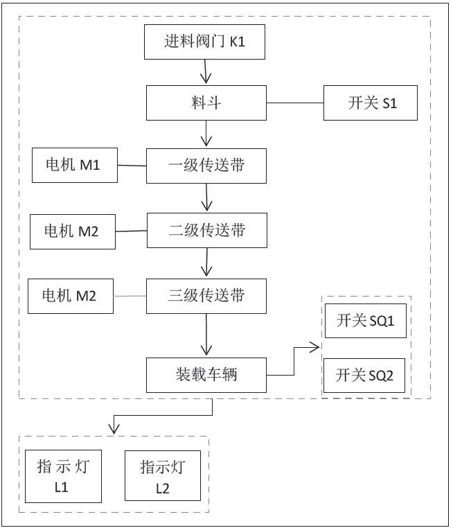
Figure 2 autoload control system control process
3. 1 presentation of the basic elements of the plc project
The control status of the autoload control system is divided into the initial state, load control, stop control. The automated load control system workflow is shown in figure 2. Initial state: the red light l1 is disconnected, the green light l2 is connected, the vehicle is loaded, the tank exit k2 is closed, the electric machine m1, m2, m3 is closed。
Vehicle loading control: (1) the material, if the material in the cauldron is missing (s1 disconnected), the feed valve k1 is open and fed after 5s. When the material is full (s1 connection), stop feeding. (2) when the vehicle enters the loading position (sq1 connection), the red light l1 is connected and the green light l2 is disconnected. At the same time, the motor m3,2s was activated after it had been activated, the generator m2 was activated after 2s and the generator m1 was activated after 2s and the pipe (k2-connected) was opened after 2s. When the vehicle was fully loaded (sq2) the combat k2 was closed, the electric m1 stopped after 2s, the electric m2 stopped after the electric m1 stopped 2s, the electric m3 stopped after the electric m2 stopped 2s, the red indicator l1 was disconnected and the green indicator l2 was connected。
Stop control: press the stop button to stop the entire system。
3. 2 project practice based on control panels
Implementation of step7-micro/win32, based on windows applications, allows efficient programming, monitoring, etc. Of s7-200 cpu. Pcs and plcs are used to connect pc computers to plcs using pc/ppi programming cables. The data transfer between the mainframe and the aircraft through the standard serial interface rs232. There is no segregation between external signals and logical circuits at rs-485 serial communications ports, and it supports no ppi communications port agreement, profibus point-to-point agreement. The ppi/mpi protocol is set at 9. 6 kbps. The main task of pc is to edit and monitor plc programs through step7-micro/win programming software. Step7-micro/win is a programming software designed for s7-200 that can be used with the windows operating system of the pc. It is powerful, easy to use and easy to learn, and teachers can guide students to easily program their projects。
The input/output points connected to the plc main panel and the corresponding presentation boards, using a simulation control panel for joint debugging of communications and systems, and establishing communications between plc and pc machines in accordance with the following steps。
(1) ensure that the communication cable between pc and cpu is connected and that the cpu operating mode selector switch is at a "term" or "stop " position。
(2) select communications from the view of the main menu or click the communications icon to show the communications settings dialogue box, indicating that the cpu is not connected。
(3) double-click in the communications settings dialogue box to update the icon, and step7-micro/win32 will check the connected s7-200 cpu station and each station connected to the communications settings dialogue box will be shown as a cpu icon
(4) double-click the station to communicate, the communication parameters of the selected station will be shown in the communication settings dialogue box。
(5) online connection with s7-200 cpu (download, upload, monitoring). The successful implementation of step7-micro/win32 and the establishment of communications with computers will allow the editing program to be downloaded to plc as follows。
(1) ensure that plc is in a cessation mode. Plc work mode switches can be followed when set to term position: check the work mode indicator on the plc and click the stop button on the toolbar if it is not stopped。
(2) click the download button on the toolbar in the stopped working mode。
(3) select all check boxes, and then click the ok button to start downloading. If the download is successful, you will be prompted to download。
(4) correct the plc type selection and then choose no to end the download process。
(5) select the type from the plc on the menu bar to display the plc type dialogue box. When you click to read cpu, step7-micro/win32 automatically reads the right value, and clicks the ok button to confirm the plc type and release the dialogue box。
(6) click the download button on the toolbar to restart the download process. When downloaded successfully, plc can be placed in running mode by clicking the run button on the toolbar. Downloading the ladder to the plc teaching simulation control board allows the program to debug。
4. Concluding remarks
In the light of the above, the plc pedagogical simulation control board, based on the assurance of pedagogical effectiveness, can systematically and visually complete the hardware connection, programming, debugging and running demonstration of the plc control system. The plc teaching simulation control board (plc) hardware structure follows the structural processes of the actual plc control system. It helps students to develop a system concept that matches actual production. It provides visual access to debugging and control results, improves the effectiveness of teaching and better meets the needs of society for plc skilled personnel。









