In applied circuits for sensors such as industrial controls, output analogue signals generally exist in the form of voltage. When a simulated signal is transmitted at long distances by means of electric voltage, a signal-source or direct-flow resistance, such as a transmission line, causes voltage decay. In order to avoid the deterioration of the signal during the transmission process, the input resistance at the receiving end of the signal may be increased, but the increased resistance at the receiving end makes the transmission route vulnerable to external electromagnetic interference, so that when a simulated signal is transmitted at a long distance, it is not possible to export it by voltage, but instead to convert the voltage output to current output。
The voltage current converter is the circuit that converts the incoming voltage signal into the current signal and is a current source controlled by the voltage. It is the conversion of the incoming voltage signal into a current signal that satisfies a certain relationship. The converted current is a constant source of an output that can be adjusted. The output current should be able to remain stable and not change as the load changes。
Here's a 0-2. 5v3. 3v5v10v15v24 to 4-20ma current transmitterCircuit design principlesI don't know。
1-voltage constant circuit
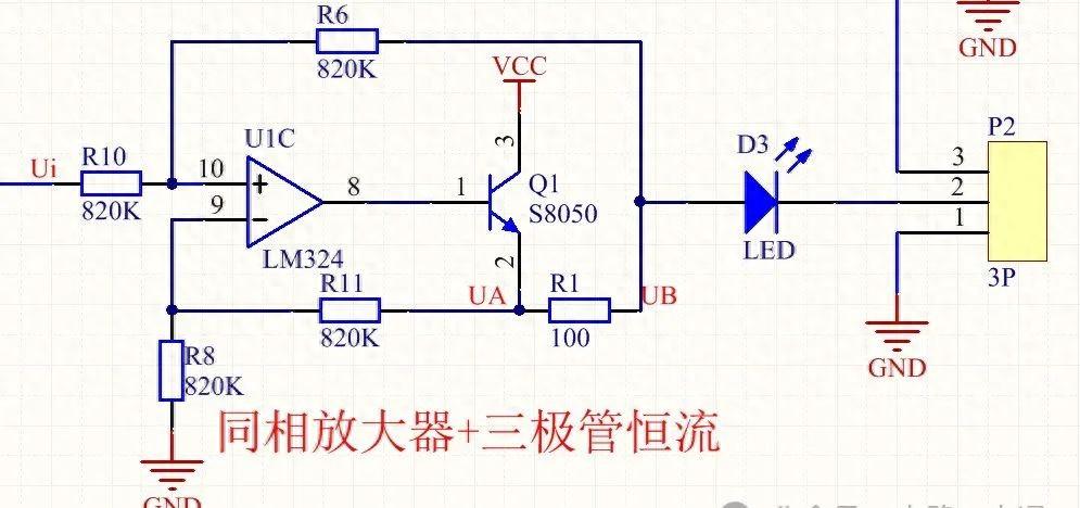
This is a pressure-controlled constant flow source consisting of discharge and tripolar tubes, which is based on negative feedback control control of discharge-out voltage to control the size of the flow of the npn-transmitting tube, thus controlling the size of the triode-output current, tripolar work and magnification, discharge and peripheral resistance forming the same amplifier, magnified by a factor of 1+ (r11/r8) = 2, vcc as a tripolar tube and distributed power source。
The voltage at the same input end of the circuit is not controlled by the external input of the ui, but by the introduction of the ub voltage through the resistance r6, i. E. The sample resistance of the r6 low voltage, which is distributed at the same input end, i. E. The 10 end voltage (ui-ub)/2 + ub, which controls the size of the output stream by controlling the size of the ui。
It is important to note that the back-level output load cannot be too large and that when the load produces a pressure drop greater than the triode power source vcc, the triode does not provide sufficient current。
2 voltage signal amplification
According to the output current range 4-20ma, the corresponding range for the reverse roll-out of the ui is 0. 4-2v, with the following figure for the first-level magnification circuit before the ui:
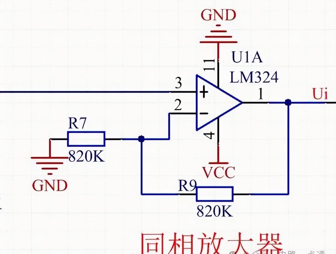
Three to zero:
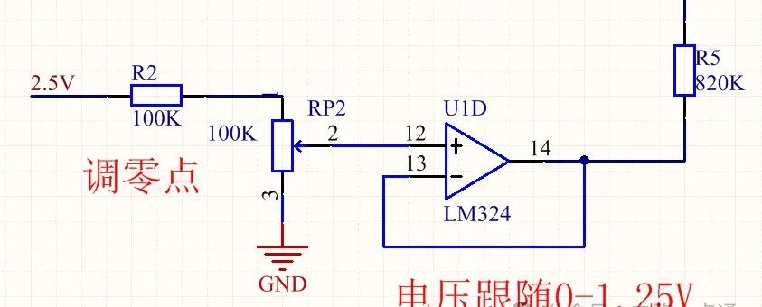
Since the current range of the modular circuit to the output is 4-20ma, it is necessary to ensure that at the input voltage of 0v ui is 0. 4v, i. E., the chargeable circuit will need to be adjusted at the same input end as the amplifier u1a. The voltage circuit voltage must be accurate and stable, not affected by voltage fluctuations of the power source. Tl 431 consists of 2. 5v as the base voltage source, which is fed via the rp2 sub-pressure of the electrical level via the follower output via r5 to the u1a input end。
In this way, the rp2 adjusts the size of the corresponding output current, and the rp2 adjusts the output current to 4ma before using the module。
4 quantities adjustment
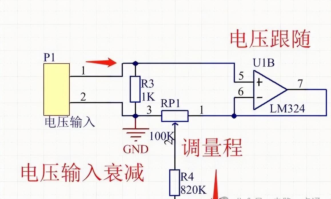
The voltage input component is produced by a follower consisting of discharge (the input resists height, the output resists small) and then the input voltage decay is performed by a biter. After a zero operation, input voltage can be adjusted to maximum and output currents can be reached by adjusting the rp1 to 20 ma。
Module 5 use steps
For example, in order to achieve the power function of 0-10v for output 4-20ma, the first step would be to adjust zero to the input voltage first, to reach 4ma by adjusting rp2 to the output voltage, then to 10m to the input voltage, and to reconcile the output voltage rp1 to 20ma, i. E. To complete the reconciliation, and to reconcile the other quantities with the above steps。
N. B.: the rear output load cannot be too large, but when the load generates a pressure drop greater than the triode power supply vcc, the charge is too large to provide sufficient current。
6 module overall rationale