


Optimised control over the exchange of gases per cylinder is achieved by the popular/odiavs variable door rise, mainly through the electronic air door lift on the exhaust cam axis and during the calibration on the inbound and exhaust door cam axis, with the engine electronic control unit determining which cam to use depending on the current engine load, with the smaller cam being used only for low rotation speed。
The following are the benefits of variable door lifts: optimize gas exchange; prevent waste gas from returning to the previous 180° exhaust tank; open the gas door earlier and fill the gas more fully; have a small amount of residual gas through high pressure in the combustion chamber; increase responsiveness; and achieve higher twists at lower rotation and higher pressure pressure。
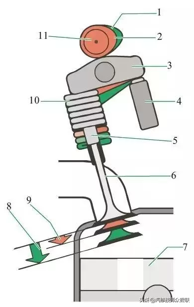
Volkswagen/ odican gas door lift
1 - cam contour; 2 - cam contour
3 - rolling-on-arms thorn claws; 4 - hydraulic poles; 5 - gas door catheters
6 -- exhaust door; 7 -- pistons; 8 -- major start-up process
9 - small start-up process; 10 - air door spring; 11 - exhaust cam axis
Cam axis structure
In order to switch between two different air-gate lifts on the exhaust cam axis, there are four removable cams (with internal flower keys) on the cam axis. Each cam contains two pairs of cams, which vary in length. Switches the two lifts through the implementer. The implementer binds the slider on each cam and moves the cam on the cam axis. Each cam has two implementers for round-trip switching between two lifts。
The spring-mounted ball in the cam axis locks the cam at its end. The slides and axle thrust bearings of the cam axis limit the movement of the cam. The structure of the mass/odiable gas gate riser cam axis is shown below。
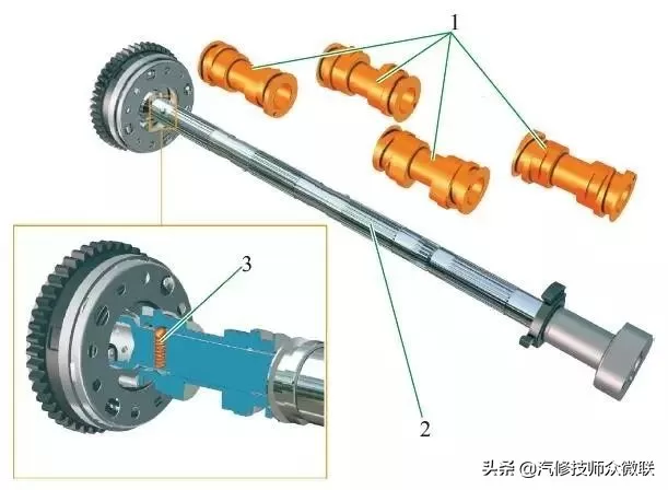
1-movable cam; 2- exhaust cam axis with external slide keys
3- lock cams with sphere and spring
Executor
Each cam on the cam axis is pushed back and forth between two switching positions, supported by two electro-magnetic valves (emps) [frost cam a/b of cylinders 1 to 4]. One of the implementers in each tank switch to a larger gas door lift, while the other switch to a smaller gas door lift。
Each implementer is activated by a local signal from the engine control unit. Electricity is provided through the main relay. The current consumption of the implementer is approximately 3a. The location structure and rationale of the implementer are illustrated below。
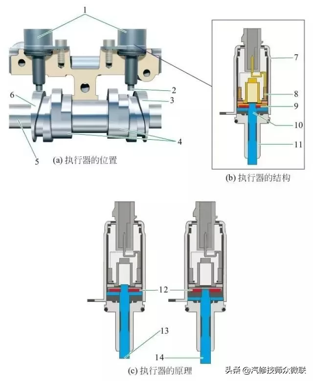
1-implementer (electromagnetic valves); 2,10-metal sales; 3,6-column slope
4 - moveable cam; 5 - exhaust cam axis; 7 - shell
8-electromagnetic wires; 9-permanent magnets; 11-conductor tubes
12 - permanent magnets; 13 - indented metal sales; 14 - carried metal sales
When the current passes through the emp, the metal is moved within 18-22 ms. The extended metal sales are integrated into the relevant slider of the cam on the exhaust cam axis and drive the slider to the corresponding switching position by rotating the cam axis. The sale is mechanically reduced by the operation of the slider (equivalent to a double slope)。
When the two implementers of the cam are activated, there is always only one metallic move on the implementer。
The position of the cam axis and the switch when the engine turns low
The position of the cam axis of the engine at the lower rotation load and the switch are shown in the figure below。
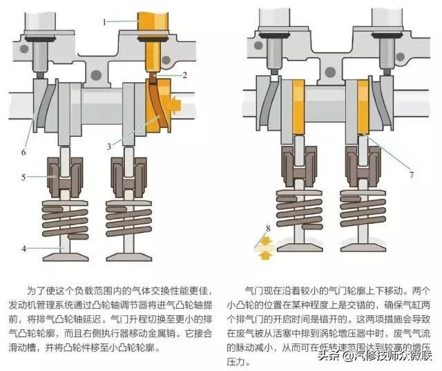
1-implementer; 2-metal sales; 3-sliding tanks
4-assessment door; 5-standing arm claws; 6-camb
7 - roll-and-roll thorn claws running on a mini cam; 8 - small trip started
Position of the engine and switch of the cam axis under partial and full load
The position of the engine at the cam axis under partial and full load and the switch are shown in the figure below。
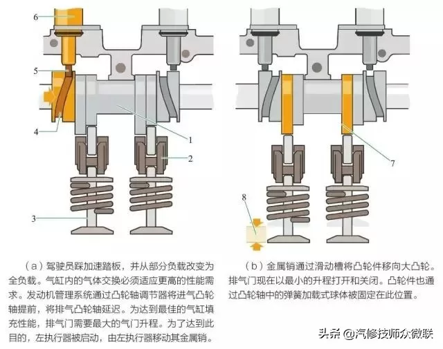
1-cam; 2-roller wrangler claw; 3-gas door
4-sliding tanks; 5-metal sales; 6-implementers
7-turkward wrangler claws on cam; 8-atmosphere door opening









