


Wireless music doorbell production is presented in a number of electronic newspapers and magazines, and many music chips are available for multiples, and in the production of our actual guidance, many beginners are very vulnerable to the destruction of electronics because they have not been exposed to electronic welding, while multiple music films, which are specialized chips, many hands-on teachers are unable to react, and are difficult to obtain locally similar substitutes for practical training for students, with the aim of improving their ability to do and learnElectronic technology, thus hoping to use generic music circuits. In response, we are introducing here a single-barrel wireless music doorbell, which uses the bj-15 type, which is the most common on the market today, and some of the manufacturers' models are: 9,300, which can be used. When assembled, the doorbell is as chart 1。
Introduction to the principles of the circuit
Charts of the principle of circuits are shown in figures 2 and 3。
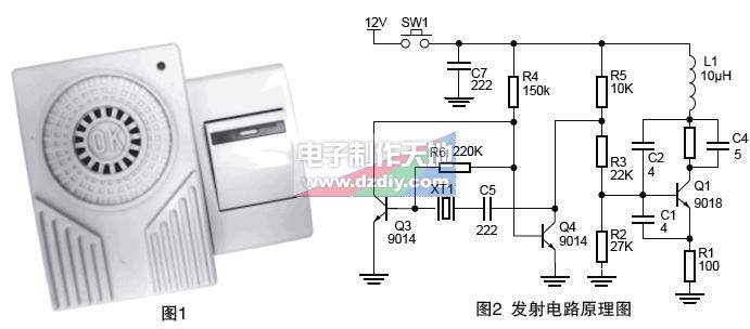
The components q3, q4 and xt1 that form the wireless launch circuits produced in figure 2 constitute low-frequency signal oscillation circuits, with frequency values determined by components such as xt1, q1, c1, c2 and c4 forming a three-point high-frequency oscillation circuit, signals generated by low-frequency signals injected through r3 to the base pole of q1, modulation of high-frequency signals, modulation of post-modulation carrier signals, ejected from the antenna on the board into the air as a remote control signal for wireless remote doorbells。
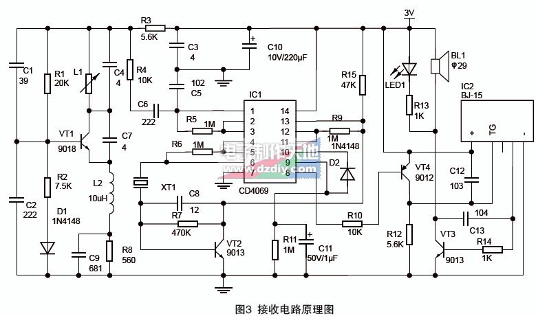
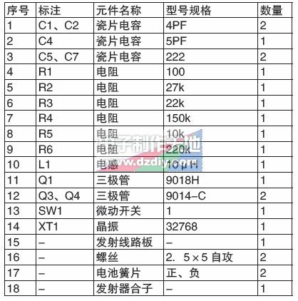
Figure 3 shows the rationale for the reception of circuits, vt1 and associated components, which constitute ultra-retroactive detection circuits, and l1 and c4 constitute an selected frequency network. To facilitate the manufacturer's debugging, this production was designed to have a part of the launch hf fixed so that the debugging could be completed by simply regulating the l1 end, and when the l1 and c4 and the intersonance frequency were consistent with the launch end, it was most resistant and had the greatest added value, while other frequency wireless signals would not be effectively amplified and would therefore be inhibited because of their discomfortation. The remote-controlled signal that is launched is amplified by a combination of r4 and c6 coupling into non-door circuits, by negative secondary feedback, from the six-foot ic1 output, xt1, vt2 etc. Consisting of selected frequency magnification circuits, where the frequency of the xt1 is consistent with the modulation frequency of the end of the launch, where only the signal from the launcher is minimally resistant, while the remaining jamming signals show high resistance and severe decline. Once the control signal from the end of the launcher has been received by the front circuit, a single steady circuit lock consisting of d2, r11, c11, etc., controls the vt4 conductor, sends a trigger signal to the music circuit ic2, makes the music circuit work, plays a song, and when a song is finished, the music stops and the system is automatically on standby. The list of launch material is shown in table 1。
Ii. Enhancements
Upon completion of this production, the reader will install some of the hf circuit elements so that the elements are as close as possible to the circuit board, i. E. Welding the elements properly into the end, and welding welding will be used to maximize the selection of products with a higher tin content. If welding is used as a welding agent, it must be kept clean on the circuit board, otherwise the longer foot of the element and more cedar on the circuit board will increase the distribution of the circuits and destabilize the high frequency oscillation sections of the circuit, thereby affecting the performance of the whole machine。
2. When installed, special attention shall be paid to the co-operation of micro-switches with plastic casings, and when the launch switch is pressed at normal times, the sound of a clean switch shall be heard, and the failure to press the switch shall be carefully checked if the micro-switches and the plastic switch are clogged when the circuit board is fixed。
3. Launcher batteries must be welded with reeds first on circuit boards and reeds. Due to the size of the metal part of the reeds and their rapid heat spread, be careful not to burn hands when going up, and when welding the reeds with the circuit boards, the area of contact must be large. Otherwise, this part of the reeds will be subject to greater mechanical force, easy to relax or fall off, while at the same time being careful that the welding on the circuit boards will not be too long, otherwise the copper skin on the circuit boards will be easily removed。
4. The c3 sign on the launcher's circuit board is intended to compensate for the position reserved for the electrical capacity and is not welded at the time of its actual installation, and therefore is not marked in the chart of the principle of the circuit; a photograph of the part of the launch is shown in figure 4。
5. Welding receiver circuit boards can be assembled using a chart of principles marked on the circuit board, in which the r9 on the circuit chart is left for functional tests, is not physically installed and is not equipped with this 1m resistance in the meta-materials, and the length of its feet must be determined in conjunction with the height of the shell when the led welding is carried out, and the normal lid is placed on it, which requires that the maker is in possession of it at the time of production, but not without regard to the height of the shell, cutting off the glowing tube directly from its feet, otherwise it is too short to see light after the cap. The receiving circuit boards that have been installed are shown in figure 5。
6. When music is integrated into circuit welding, care is taken that the iron contact is not too long, and if conditions are met, the iron is best placed on the floor, the first foot of a musical film may be stinged first, not too much, otherwise it will not be possible to insert a slot on the board, the music table and the board will be welded all over the board, the first foot will be welded to the board and position it, and then the last foot will be welded, and the music table will be firmly placed on the board, and it will be much easier to weld the other steps. The circuit boards and power and horn lines produced are shown in figure 6。
System debugging
1. Debugging of the launcher: when all components are installed, the circuit board is loaded into the remote control box to check whether the micro-movement switch can hear a clear switch。
When instruments such as frequency meters or spectrum spectrometers are in place, they can detect the presence of high-frequency radio waves by means of a remote control device, which, in the absence of these instruments, can also be used as a radio or computer sound, and when presses the remote control, the sound of “creaking, squeaking” can be heard, indicating that the launch is normal and generally successful as long as the components are correctly installed and the circuit boards of the components are free of tin or welding。
3. Debugging of receivers: once all components have been installed, the circuit boards are loaded into plastic casings, and the power-wire connection must be made to be polar and not reverse。
4. Loading battery no. 5 in section 2 and short-linking vt4 launch poles and ccds, and normally hearing music, should the horn lines not sound, should be carefully checked for welding, and for the drawings of music films, welding, etc。
5. Once all of the above is normal, the connection between the launch and the receipt can be made, the launcher can be placed next to the receiver, the remote control press, if there is a sound, then the distance between the two can be increased, then the callable senses on the receiver can be adjusted with a sensory screw knife, if there is no reaction, until the remote control receiver will ring, continue to increase the distance, and the above-mentioned method is repeated, and the commissioning of the remote control bell will be completed when the remote control bell can be reliably controlled at a distance of more than 20 metres。









